Membuat Saklar Pintar Menggunakan ESP8266
Tulisan ini dibuat untuk laporan ujian praktek mata pelajaran IPS dan IPA.
Saya membuat sebuah saklar pintar berbasis Internet of Things (IoT). Saklar ini dapat dikontrol dari jarak jauh menggunakan aplikasi atau website dengan bantuan koneksi internet.
Tujuan dari pembuatan saklar pintar ini adalah untuk memudahkan pengguna dalam menghidupkan atau mematikan perangkat elektronik dari jarak jauh tanpa harus melakukan kontak fisik secara langsung. Saklar pintar ini juga bisa untuk membuat jadwal yang dapat menghidupkan dan mematikan perangkat elekronik secara otomatis.
Software
- Arduino IDE
- Driver CH340G
Alat dan Bahan
- Laptop (Ubuntu 20.04)
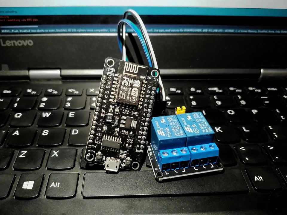
- ESP8266 Nodemcu v3.0 Lolin
- Relay 2 channel
- Kabel jumper female to female
- Kabel USB A ke Micro USB
- Jaringan WiFi (Internet)
- Akun Sinric Pro
Langkah Pembuatan
Tambahkan board ESP8266 ke Arduino IDE
File > Preferences > Settings
Tambahkan URL ini ke Additional Boards Manager URLs
https://arduino.esp8266.com/stable/package_esp8266com_index.jsonInstall board ESP8266
Tools > Board > Boards Manager
Install board esp8266 dari ESP8266 Community
Install library sinric
Tools > Manage Libraries
Install library SinricPro dan SinricPro_Generic
Buat file baru di Arduino IDE dan salin kode berikut
#ifdef ENABLE_DEBUG
       #define DEBUG_ESP_PORT Serial
       #define NODEBUG_WEBSOCKETS
       #define NDEBUG
#endif

#include <Arduino.h>
#ifdef ESP8266
       #include <ESP8266WiFi.h>
#endif
#ifdef ESP32
       #include <WiFi.h>
#endif

#include "SinricPro.h"
#include "SinricProSwitch.h"

#include <map>

#define WIFI_SSID         "YOUR-WIFI-SSID"
#define WIFI_PASS         "YOUR-WIFI-PASSWORD"
#define APP_KEY           "YOUR-APP-KEY"
#define APP_SECRET        "YOUR-APP-SECRET"

#define TACTILE_BUTTON 1

#define BAUD_RATE   9600

#define DEBOUNCE_TIME 250

#ifdef ESP8266
#define RELAYPIN_1 D1
#define RELAYPIN_2 D2
#define RELAYPIN_3 D3
#define RELAYPIN_4 D4
#define SWITCHPIN_1 D8
#define SWITCHPIN_2 D7
#define SWITCHPIN_3 D6
#define SWITCHPIN_4 D5
#endif

#ifdef ESP32
#define LED_BUILTIN 2

#define RELAYPIN_1 16
#define RELAYPIN_2 17
#define RELAYPIN_3 18
#define RELAYPIN_4 19
#define SWITCHPIN_1 25
#define SWITCHPIN_2 26
#define SWITCHPIN_3 22
#define SWITCHPIN_4 21
#endif

typedef struct {
  int relayPIN;
  int flipSwitchPIN;
} deviceConfig_t;

std::map<String, deviceConfig_t> devices = {
    //{deviceId, {relayPIN,  flipSwitchPIN}}
    {"SWITCH_ID_NO_1_HERE", {  RELAYPIN_1, SWITCHPIN_1 }},
    {"SWITCH_ID_NO_2_HERE", {  RELAYPIN_2, SWITCHPIN_2 }}
};

typedef struct {
  String deviceId;
  bool lastFlipSwitchState;
  unsigned long lastFlipSwitchChange;
} flipSwitchConfig_t;

std::map<int, flipSwitchConfig_t> flipSwitches;

void setupRelays() {
  for (auto &device : devices) {
    int relayPIN = device.second.relayPIN;
    pinMode(relayPIN, OUTPUT);
  }
}

void setupFlipSwitches() {
  for (auto &device : devices)  {
    flipSwitchConfig_t flipSwitchConfig;

    flipSwitchConfig.deviceId = device.first;
    flipSwitchConfig.lastFlipSwitchChange = 0;
    flipSwitchConfig.lastFlipSwitchState = false;

    int flipSwitchPIN = device.second.flipSwitchPIN;

    flipSwitches[flipSwitchPIN] = flipSwitchConfig;
    pinMode(flipSwitchPIN, INPUT);
  }
}

bool onPowerState(String deviceId, bool &state)
{
  Serial.printf("%s: %s\r\n", deviceId.c_str(), state ? "on" : "off");
  int relayPIN = devices[deviceId].relayPIN;
  digitalWrite(relayPIN, !state);
  return true;
}

void handleFlipSwitches() {
  unsigned long actualMillis = millis();
  for (auto &flipSwitch : flipSwitches) {
    unsigned long lastFlipSwitchChange = flipSwitch.second.lastFlipSwitchChange;

    if (actualMillis - lastFlipSwitchChange > DEBOUNCE_TIME) {

      int flipSwitchPIN = flipSwitch.first;
      bool lastFlipSwitchState = flipSwitch.second.lastFlipSwitchState;
      bool flipSwitchState = digitalRead(flipSwitchPIN);
      if (flipSwitchState != lastFlipSwitchState) {
#ifdef TACTILE_BUTTON
        if (flipSwitchState) {
#endif
          flipSwitch.second.lastFlipSwitchChange = actualMillis;
          String deviceId = flipSwitch.second.deviceId;
          int relayPIN = devices[deviceId].relayPIN;
          bool newRelayState = !digitalRead(relayPIN);
          digitalWrite(relayPIN, newRelayState);

          SinricProSwitch &mySwitch = SinricPro[deviceId];
          mySwitch.sendPowerStateEvent(newRelayState);
#ifdef TACTILE_BUTTON
        }
#endif
        flipSwitch.second.lastFlipSwitchState = flipSwitchState;
      }
    }
  }
}

void setupWiFi()
{
  Serial.printf("\r\n[Wifi]: Connecting");
  WiFi.begin(WIFI_SSID, WIFI_PASS);

  while (WiFi.status() != WL_CONNECTED)
  {
    Serial.printf(".");
    delay(250);
  }
  digitalWrite(LED_BUILTIN, HIGH);
  Serial.printf("connected!\r\n[WiFi]: IP-Address is %s\r\n", WiFi.localIP().toString().c_str());
}

void setupSinricPro()
{
  for (auto &device : devices)
  {
    const char *deviceId = device.first.c_str();
    SinricProSwitch &mySwitch = SinricPro[deviceId];
    mySwitch.onPowerState(onPowerState);
  }

  SinricPro.restoreDeviceStates(true);
  SinricPro.begin(APP_KEY, APP_SECRET);
}

void setup()
{
  Serial.begin(BAUD_RATE);
  setupRelays();
  setupFlipSwitches();
  setupWiFi();
  setupSinricPro();
}

void loop()
{
  SinricPro.handle();
  handleFlipSwitches();
}
Sumber: MultiSwitch_advance.ino (dengan beberapa perubahan)
Buat akun Sinric Pro
Buat akun baru di Sinric Pro
Buka menu Rooms di Sinric Pro
Isi Room Name dan Description
Room Name: Experiment IoT
Description: For IoT experiment things.
Home: Home
Buka menu Devices di Sinric Pro
Klik tombol Add Device dan isi Device Information
Device Name: Switch 1
Description: Switch 1 for ESP8266 Smart Switch.
Device Type: Switch
App Key: Default
Room: Experiment IoT
Lakukan hal yang sama untuk Switch 2
Salin ID device yang sudah dibuat ke kode berikut
std::map<String, deviceConfig_t> devices = {
	//{deviceId, {relayPIN,  flipSwitchPIN}}
	{"SWITCH_ID_NO_1_HERE", {  RELAYPIN_1, SWITCHPIN_1 }},
	{"SWITCH_ID_NO_2_HERE", {  RELAYPIN_2, SWITCHPIN_2 }}
};
Isi kode berikut dengan nama dan password WiFi yang akan digunakan
#define WIFI_SSID         "YOUR-WIFI-SSID"
#define WIFI_PASS         "YOUR-WIFI-PASSWORD"
Hubungkan ESP8266 ke laptop menggunakan kabel USB
Pilih board pada Arduino IDE
Tools > Board > ESP8266 Boards (3.1.1) > NodeMCU 1.0 (ESP-12E Module)
Pilih port pada Arduino IDE
Tools > Port > /dev/ttyUSB0
Upload kode ke ESP8266
Tunggu proses compile selesai dan selesai terupload
Hubungkan pin ESP8266 dan relay dengan kabel jumper
| Pin ESP8266 | Pin Relay |
|---|---|
| G | Gnd |
| VV | Vcc |
| D1 | In1 |
| D2 | In2 |
Test menggunakan Dashboard Sinric Pro
Coba untuk menghidupkan dan mematikan switch, lampu relay akan mati saat off dan akan hidup saat on.
Member discussion